


From spacing and siting to mounting and integration, designing a radar-based detection system requires line-of-sight thinking at every stage
Navtech Radar – ITS European Congress Istanbul – Booth F13
Navtech Radar explains how 360-degree radar replaces snapshot views with continuous corridor coverage, providing reliable incident detection across the entire highway even in poor visibility. For consultants and integrators, this calls for a different design approach, beginning at the specification stage. This article explains how to specify it, from coverage and spacing through geometry, mounting and control-room integration.
Coverage planning
When designing with 360-degree radar, coverage planning begins with outcomes, not hardware. This means specifying the incident set to be detected and defining the required detection performance metrics. These metrics then inform how radars are spaced and placed along the corridor.
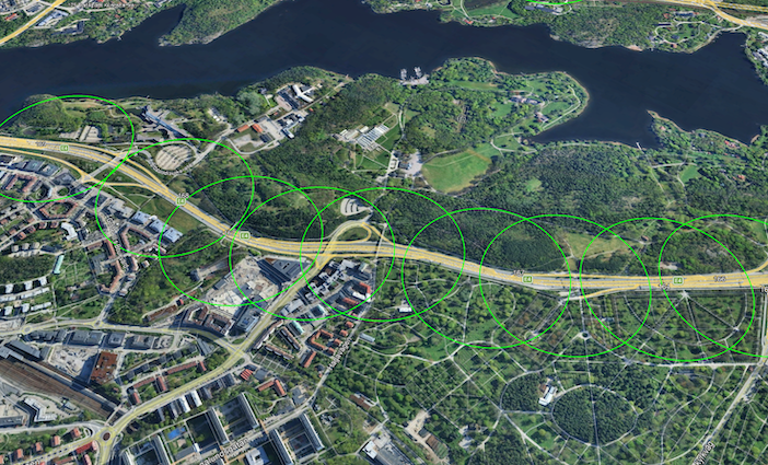
360-degree radar has a much broader and more extensive field of view than other highway detection technologies, with full coverage of the road space being a primary objective of system design. This is difficult and costly to achieve with more traditional technologies, yet it is fundamental to the choice of 360-degree radar.
Mounting pre-requisites are another aspect of coverage planning. Where only existing infrastructure can be used, this is factored into the design from the outset. Overall, maximising the use of each radar is central to placement decisions, with 360-degree long-range sensors able to monitor all carriageways within range, as well as adjacent ramps. This ensures the system meets required performance metrics.
Geometry and siting
Because radar requires line of sight, road shape and surroundings govern radar placement. On curves, mounting on the outside of the bend maintains sight down the carriageway and makes the most of the radar’s long range. Where embankments, elevation changes or carriageway splits constrain line of sight, sensors can be placed closer together to remove shadowing.
It’s important to review the structural envelope around each radar site and avoid occlusions from signs, bridge columns and seasonal vegetation growth. Mounting radar close to the road, rather than set back, is often optimal for this reason, and starting radar placement around key infrastructure such as bridges can help achieve the best layout.
Treat ramp merges and diverges as key locations, since a 360-degree field of view allows monitoring to extend across these areas within the same design, reducing the risk that an incident, such as wrong-way driving or queuing, begins outside the monitored view. Alternatively, radar can be placed specifically to cover on and off ramps.
Mounting and integration
Mounting at around 4.5 metres provides an effective view across running lanes and shoulders. A floating-plate bracket allows fine horizontal adjustment of the device alignment, while careful levelling at commissioning keeps the beam aligned along the carriageway in all directions for optimal coverage. Once in place, the radar requires no hardware maintenance over its 10+ year product life.
360-degree radar can be mounted on existing infrastructure such as gantries, though standard lamp columns are generally too flexible. Each unit requires a permanent 24V DC supply and ethernet or power over ethernet to a nearby roadside switch, with no additional cabinet controller required. Using roadside networking, radars then communicate in real time with centralised processing software.
From a central platform, Navtech’s ClearWay solution integrates with major video and traffic management systems for ease of use and improved operational efficiency. It can also output traffic data such as volume, speed and occupancy, reducing the need for multiple roadside technologies.
Experience in design
Proven projects show how these principles translate into day-to-day resilience. In Sweden, Trafikverket’s Radar Incident Detection System (RIDS) includes 121 radars deployed across 42.6km of motorway on the E4, E18 and E20, delivering reliable stopped-vehicle detection in extreme winter conditions, including snow and fog. Following the initial deployment on the E4, the system was expanded over time, with the most recent addition of 29 radars in 2024.
The experience underlines how detection and performance requirements, spacing, siting and integration choices combine to sustain coverage across an entire corridor.
Every stretch of highway is unique, and each project has specific performance and detection requirements, so these notes should be treated as a starting point. Navtech’s engineering team works with consultants from early modelling through site survey and integration, and where Navtech designs the system, performance will be guaranteed against agreed detection metrics – allowing designers to focus on the outcomes that matter most to road operators.


